Gantry Electronics & Firmware
How a Raspberry Pi 4, two ESP32s, four stepper drivers and a handful of sensors are wired together and taught to talk, so a 6-metre gantry goes exactly where it's told.
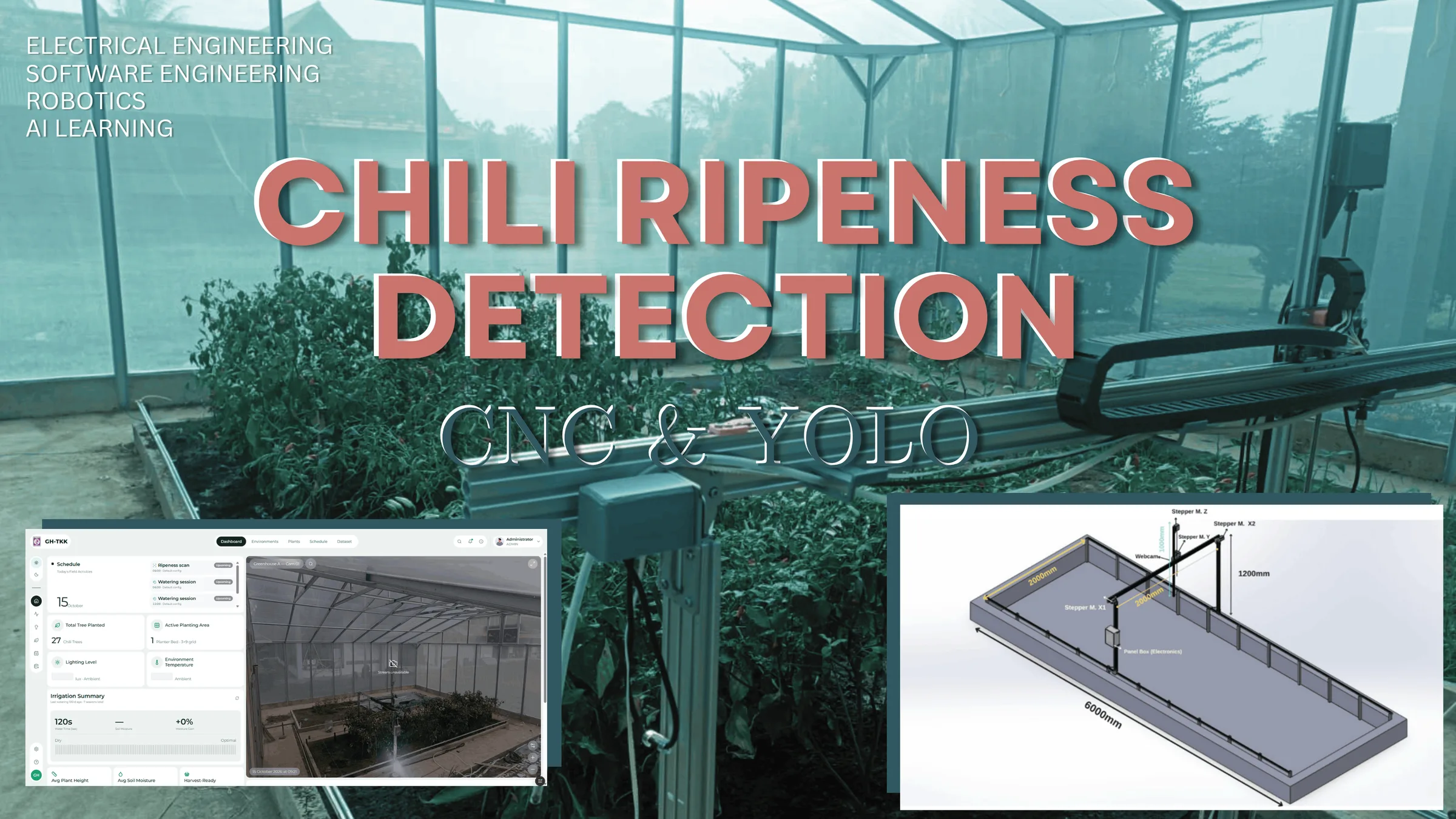
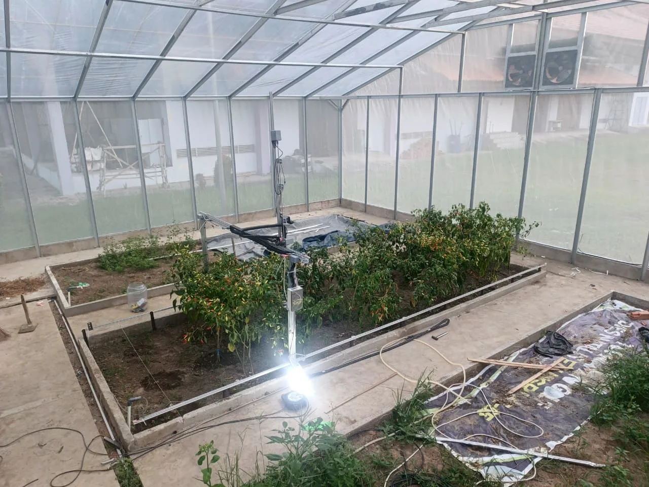
The chili gantry is three projects stacked on each other: a machine, a model and a dashboard. This one is the layer in between, where software instructions become current through a motor coil. It covers the power rails and the panel box, the pin map and the custom board, and the two small protocols that let a Raspberry Pi command microcontrollers it can't afford to trust blindly.
The rule that shaped everything: the Pi is the brain, the ESP32 is the machine. The Pi decides where to go and why, while the ESP32 owns timing-critical work like step pulses, limit switches and PWM, and never makes a decision on its own. Every piece of the wiring and firmware follows from keeping that line clean.
Results
80 / 400
Steps per mm on the belt axes / lead-screw Z
0.47 mm
Mean X positioning error over a 5.6 m run
0.03 mm
Worst homing deviation across 10 runs per axis
11
Serial commands are the entire Pi → ESP32 vocabulary
Who controls what
Raspberry Pi 4
Runs the FastAPI service, the camera and YOLOv11, and sequences every session. Talks to ESP32 #1 over USB (/dev/ttyUSB0) and ESP32 #2 over its hardware UART on GPIO 14/15 (/dev/ttyAMA0), both at 115200 baud.
ESP32 #1: motion
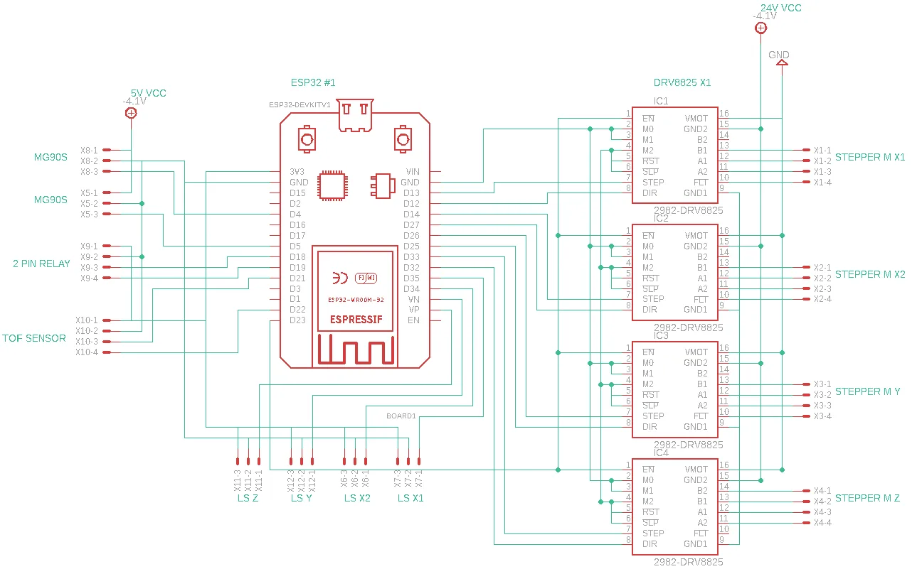
Generates step pulses for four DRV8825 drivers, drives the pan-tilt servos with 50 Hz LEDC PWM, reads four limit switches and the ToF sensor over I²C, and switches the valve and pump relays.
ESP32 #2: soil
Reads the capacitive soil-moisture probes along the bed and answers READ requests from the Pi.
Webcam
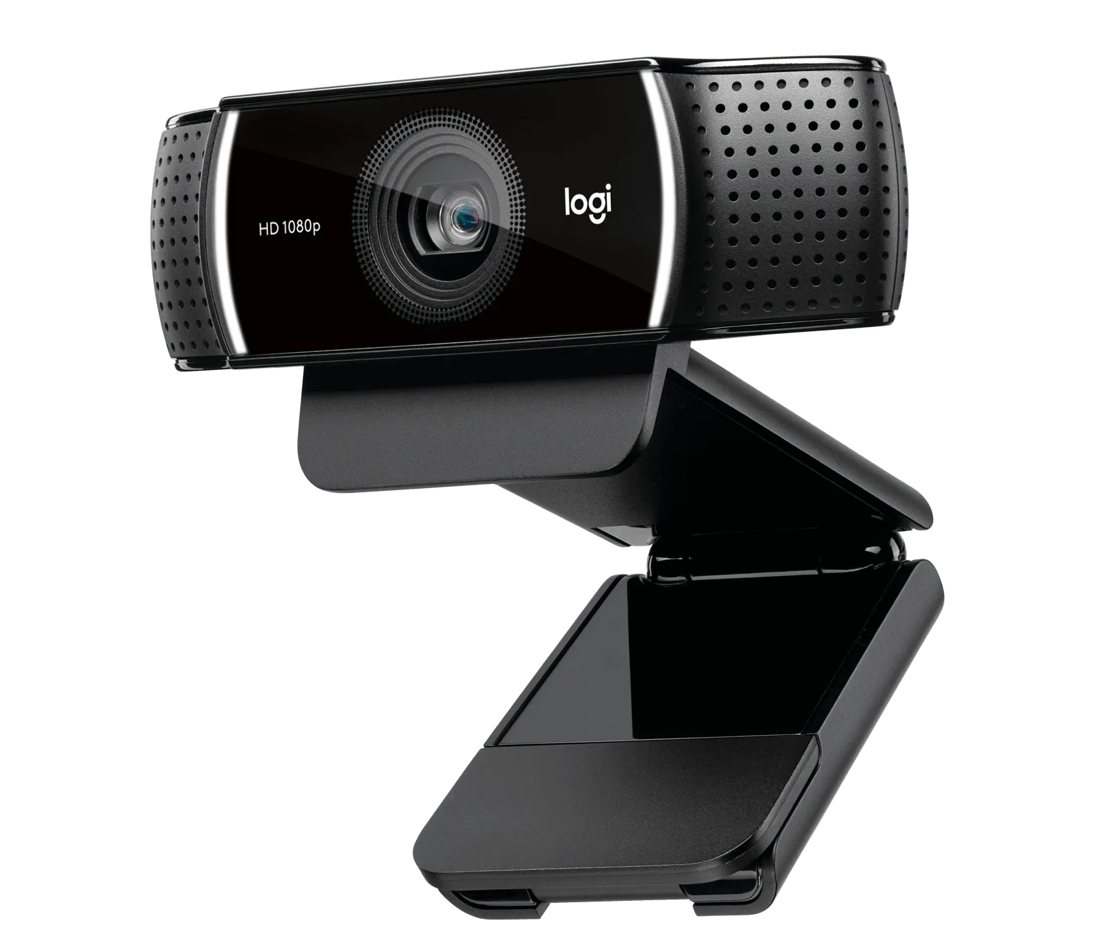
A Logitech C922 on USB, captured on the Pi at its native 1920 × 1080 MJPG mode and cropped there, so the ESP32 never touches image data.
Power and the panel box
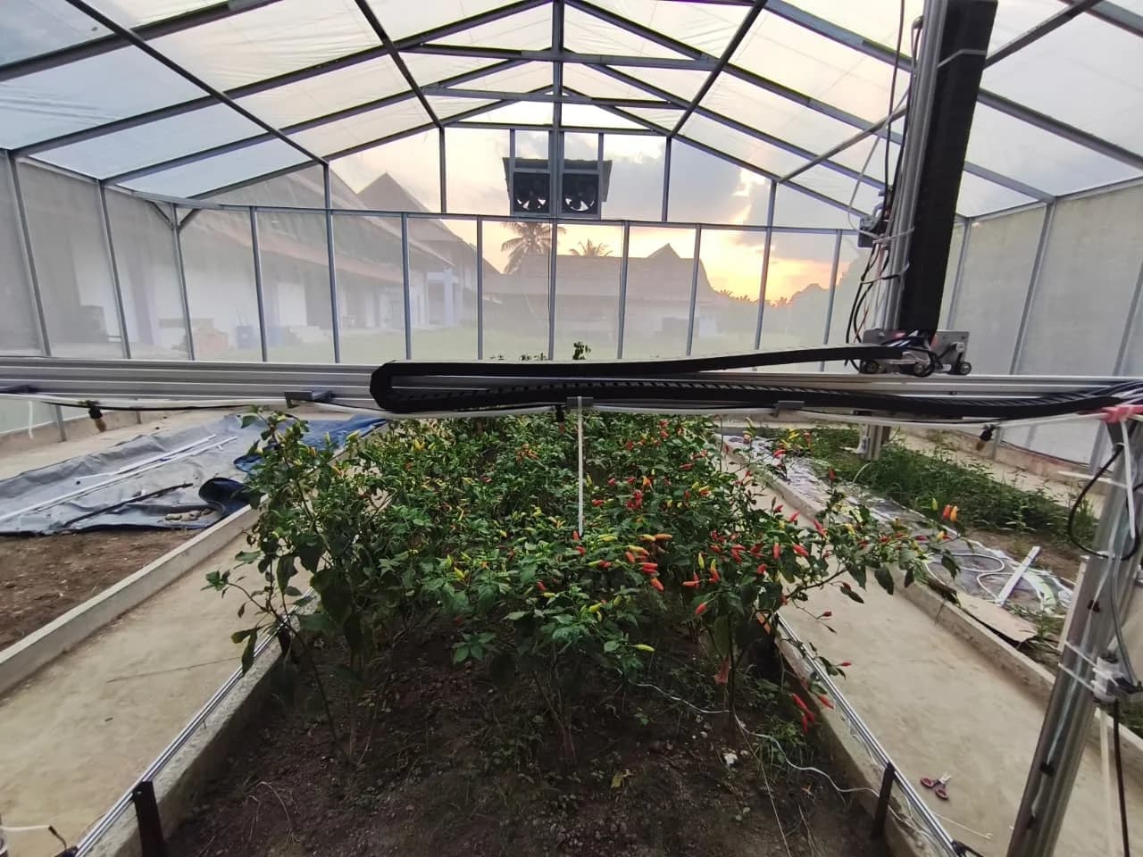
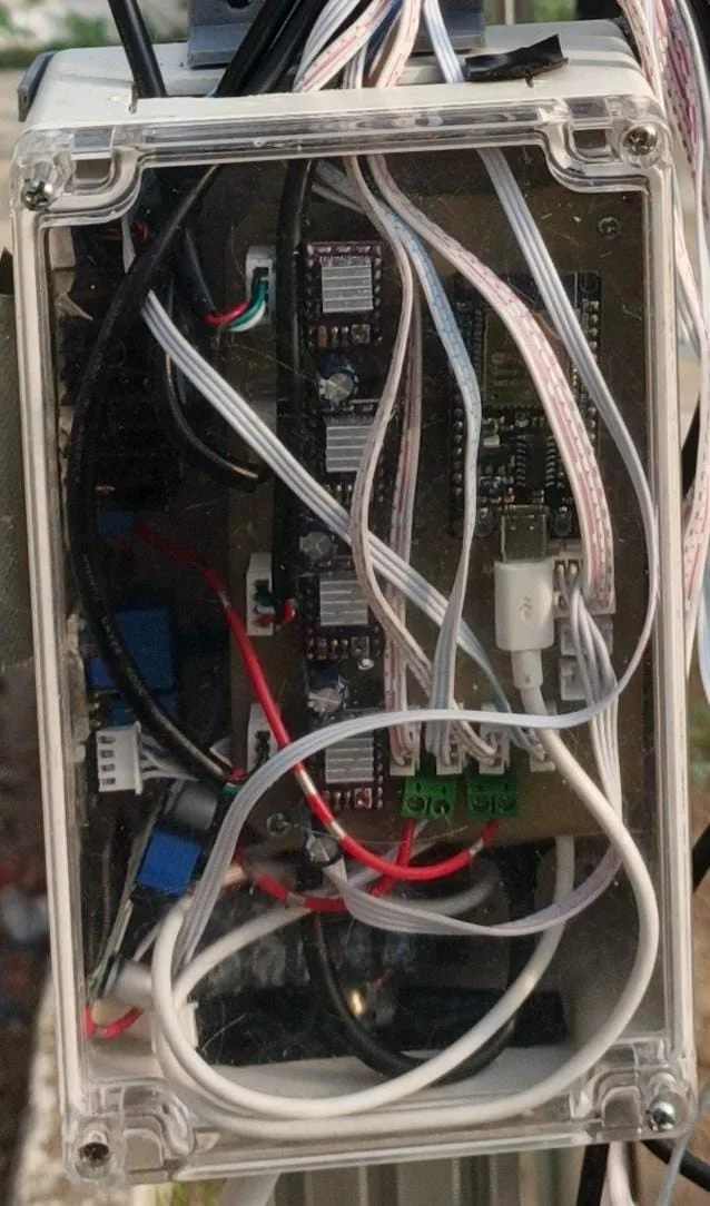
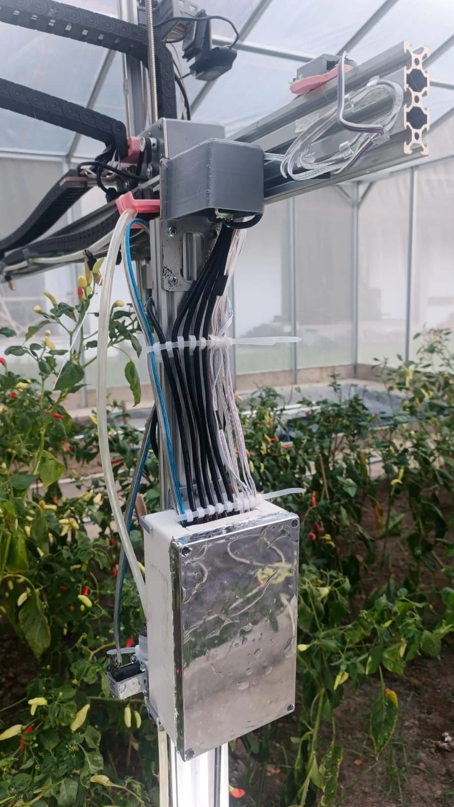
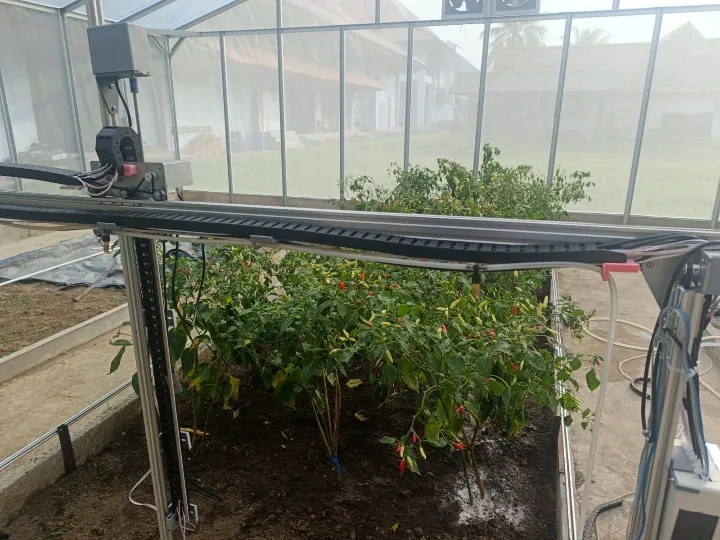
Everything electronic rides on the gantry in a single sealed enclosure bolted to one of the X columns, so it moves with the machine and the motor leads stay short. A 24 V supply feeds the DRV8825 motor rails directly, while two buck converters step it down to 12 V for the solenoid valve side and 5 V for the logic, the relays and the servos.
The ESP32 and the four stepper drivers sit on a custom PCB mounted over the Raspberry Pi, with screw terminals for the motors and a row of headers for the four limit switches. Bundled cables climb the column to the motors and sensors, and drag chains carry them, along with the irrigation hose, as the carriage moves.
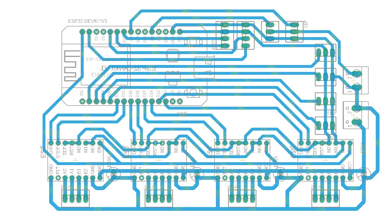
The pin map
Steppers
STEP/DIR pairs on GPIO 12/13 (X1), 14/27 (X2), 26/25 (Y) and 33/32 (Z). One shared EN line on GPIO 23 arms or releases all four drivers at once.
Limit switches
On input-only GPIO 36, 39, 34 and 35 with pull-ups: one each for X1, X2, Y and Z. A pressed switch pulls the line low.
Servos and ToF
Pan and tilt on GPIO 4 and 5 (500–2500 µs pulses for 0–180°). The ToF sensor shares I²C on GPIO 21/22.
Relays
GPIO 19 for the solenoid valve and GPIO 18 for the water pump, both driven low at boot so nothing waters on a reset.
From millimetres to steps
All four motors are 200-step NEMA17s at 1/16 microstepping: 3,200 microsteps per turn. On X and Y a 20-tooth GT2 pulley moves the belt 40 mm per turn, so one millimetre is 80 steps. Z runs on a T8 lead screw, 2 mm pitch with four starts, for 8 mm per turn and 400 steps per millimetre. That's five times finer, and the screw holds the camera's height when the drivers let go.
A MOVE scales each axis's speed and acceleration by its share of the longest leg, so X, Y and Z start and arrive together in a straight line. The two X motors get identical targets and profiles, which is what keeps the 2 m cross-beam square as it travels.
A protocol a human can read
Pi and ESP32 #1 speak plain text, one line per message. The Pi sends a command with key=value arguments, like MOVE x=1050 y=300 z=50 speed=150, and the ESP32 answers OK with a small JSON body or ERR with a reason. The whole vocabulary is eleven commands: PING, MOVE, HOME, POS, STOP, EN, RELAY, LIMITS, TOF, SERVO and SERVO_GET.
MOVE is asynchronous. The ESP32 accepts it with OK, keeps stepping, and sends a separate DONE line with the final position when every motor has stopped. Because its loop keeps reading serial while moving, the Pi can ask for TOF readings mid-move, and each answer is stamped with the current X, Y and Z. That's how the watering pass measures plant heights in one continuous sweep instead of stopping over every plant. ESP32 #2 uses the same style (PING, READ sensor=all) on the UART.
On the Pi, one thread owns each serial port behind a lock, so only one command is ever in flight. Quick commands time out after 10 seconds and moves after 300, so a silent ESP32 raises an error instead of hanging a session forever.
Homing and limit switches
HOME runs Z, then Y, then X, so the camera is lifted clear before anything moves sideways. Each axis searches toward its switch at 90 mm/s, backs off 3 mm at 6 mm/s so the switch releases cleanly, and zeroes there. X homes both motors together, and each stops on its own switch, which squares the gantry every time it's homed.
The limit cables run metres alongside stepper wiring, and early on motor noise was enough to fake a switch hit. Every switch read is now debounced: the line has to stay low for 5 ms before it counts. During a normal MOVE a confirmed hit stops the axis, latches an emergency stop and reports ERR limit_triggered with the axis and position, which the Pi treats as fatal for the session.
Failing safe
Drivers off by default
EN is held high at boot. The Pi arms the drivers at the start of a session and releases them at the end, on a stop or on an error, so the motors are never energised while idle.
Emergency stop
STOP halts every axis and cuts EN in the same instant; the Pi follows with EN off and both relays off. Each step is best-effort, so a stop does as much as it can even mid-command.
No surprise resets
Opening a USB serial port on Linux pulses DTR and RTS, which resets an ESP32. The Pi opens the port with both lines held low, so connecting never reboots the motion controller mid-move.
Cold-boot tolerant
After a power cut the Pi can boot before the USB-serial chip appears. It keeps retrying open + PING for 30 seconds, and pings again before arming the motors, instead of needing a manual reboot.
Closing the loop on water
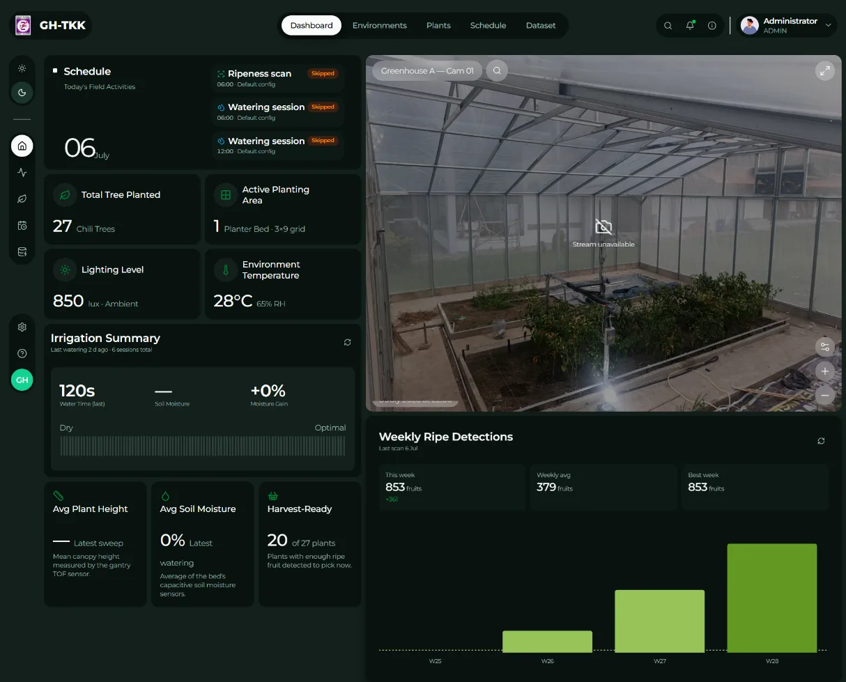
The watering pass ties both ESP32s together. The ToF sweep gives the tallest plant, ESP32 #2 gives soil moisture from all three probes, and an interval type-2 fuzzy controller on the Pi turns those into a single duration. It has five growth stages from seedling to production, five moisture levels from very dry to very wet, a 25-rule table and Karnik–Mendel type reduction, producing 0 to 120 seconds of water. The Pi then switches the pump on through ESP32 #1 and steps along the bed, opening the solenoid for that long at each stop. If the inputs ever fall outside every membership function, the answer defaults to zero: a glitched sensor can't flood the bed.
Built with
- ESP32 (Arduino core v3)
- AccelStepper
- DRV8825
- NEMA17
- T8 lead screw
- GT2 belt
- MG90S
- VL53L0X ToF
- Capacitive soil sensors
- Raspberry Pi 4
- Python
- pySerial
- FastAPI
- 24 V / 12 V / 5 V rails
Related Work